@terry
Forum Replies Created
-
AuthorPosts
-
August 1, 2024 at 4:11 pm #30030
Hi there,
Thanks for your input, could you please send me a note at Terry.xu@ecotron.ai so I can send simulink model reference for you?
Best,
Terry
February 28, 2024 at 7:12 pm #27482Hi Michael,
I will have a list for you shortly, thanks for your patience.
Best,
TerryJuly 14, 2023 at 4:52 pm #24380July 14, 2023 at 4:52 pm #24377July 14, 2023 at 4:51 pm #24374Please see EV2106B01 DEMOfor your reference, it’s not EV2106B06 demo but can be used as a reference.
Path:
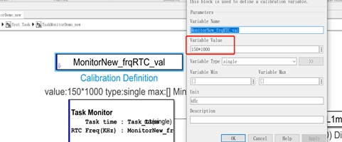
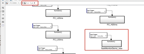
:\softwaer\ecocoder\V2.9.12R3\Toolbox\DemoAndTest\testModel\T_EV2106B01_V1.0DEMO as shown Figure1, there is a task monitoring and task Load rate DEMO
Please according to EcoCoder manual to set the right freq according to the platform you are using. (Figure 2)
And the consequence of hardware fails to execute the calculations during a task will be, potential task lag and inaccurate task time.
Best,
Terry
May 31, 2023 at 4:48 pm #23715Thanks for reaching out, please be free to ask more questions.
Best,
TerryMay 31, 2023 at 4:47 pm #23713We think you can use the timer or delay in Simulink generic blocks, but I will double check with our team and get back.
Best,
Terry
May 11, 2023 at 10:36 pm #23341Hi, j1939 block will be provided and charged separately, please talk with your contact in our side to get more information.’
Best,
Terry
-
This reply was modified 3 years, 2 months ago by
 Terry Xu.
May 11, 2023 at 10:35 pm #23339just sent you, please let me know if any further questions.
May 9, 2023 at 4:58 pm #23291Sorry that I think diagnostic voltage can’t be changed and in your case it’s still 2V.
Best,
Terry
May 4, 2023 at 5:51 pm #232231. Controller pin switch to level-high, then the output of pin should be 5V. It should be noted that the high side(on) is the power supply voltage; Low side(on) is 0V
2. You attempted to switch three ports, all of which were 0V-2V. That’s because the low side of port 95 and 109 was 0V when the port was on, and there is a diagnostic voltage of 2V when the port was off. However, pin 98 should be the power supply voltage when it was opened, and there was a diagnostic voltage of around 2V when it was closed.
3. Are you trying to get an PWM output? It is necessary to add a pull-down circuit on the high side and a pull-up resistor on the low side to form a PWM output circuit. Unfortunately, the high and low sides of our controller do not have this configuration.
May 4, 2023 at 4:54 pm #23219please leave your email so I can send you a license debugger.
best,
Terry
May 3, 2023 at 8:57 pm #23216Hi there,
Sorry that our tech team is off the office till tonight,
Please let me get back to you shortly.
Best,
Terry
May 3, 2023 at 8:52 pm #23214Hi there,
Our Software team is off the office till tonight, let me get back to you shortly.
Best,
Terry
April 27, 2023 at 5:58 am #23178Hi there,
When using EcoCoder loader, did you see that Activation is completed window?
-
This reply was modified 3 years, 2 months ago by
-
AuthorPosts