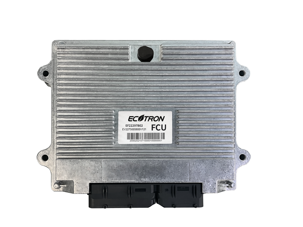
FCU - Fuel Cell Control Unit
Introduction
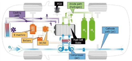
A Fuel Cell Engine (FCE) is a complex, multidisciplinary system that integrates multiple subsystems and control functions. As the core controller of the FCE, the Fuel Cell Control Unit (FCU) requires strong computing and processing capabilities, as well as a rich set of I/O interfaces, to effectively manage and coordinate these subsystems. This ensures safe, reliable, and efficient power generation from the fuel cell system over extended operating periods.
Features:
- Based on the automotive grade 32-bit MCU Infineon AURIX™ series TC27xT platform, with multi-core architecture.
- The design and development of software, hardware, and control strategy comply with ISO26262 functional safety requirements. With a built-in safety monitoring chip, our FCU is ASIL-D rated.
- Built-in basic software (BSW) supports automatic code generation tool EcoCoder (rapid prototyping), and all popular input/output of a typical fuel cell system. BSW is packaged in the MATLAB/Simulink environment, and users can develop control strategies with 100% model-based design methods.
- Equipped with a CAN bus-based software flashing tool, which is guided by the bootloader flashed into the microcontroller in advance.
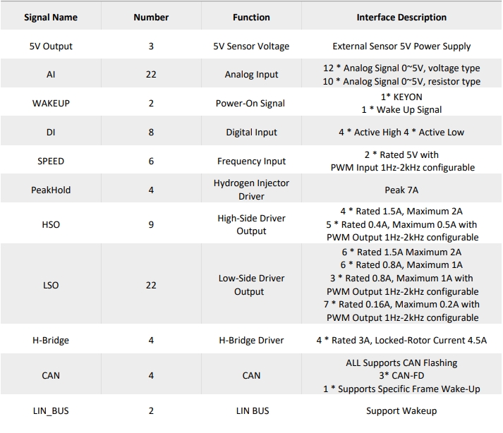
- Gas path management: Precise control of the hydrogen flow, airflow, pressure, humidity, and temperature required by the fuel cell system.
- Water and heat management: Precise control and adjustment of the circulation, heating, heat dissipation, air temperature, cooling water temperature to improve the power efficiency and reliability of the fuel cell system.
- Electrical management: Monitoring the battery pile voltage and current, adjust the output power, and control the fuel voltage within a reasonable range, manage the residual power, and provide the voltage and current protection.
- Data communication: Communicating with other subsystems, interchange important data and control signals.
- Fault diagnosis: Capable of perform fault diagnosis, raise warning, and initiate protection routine for various subsystems.