VCU - Vehicle Control Unit
Introduction
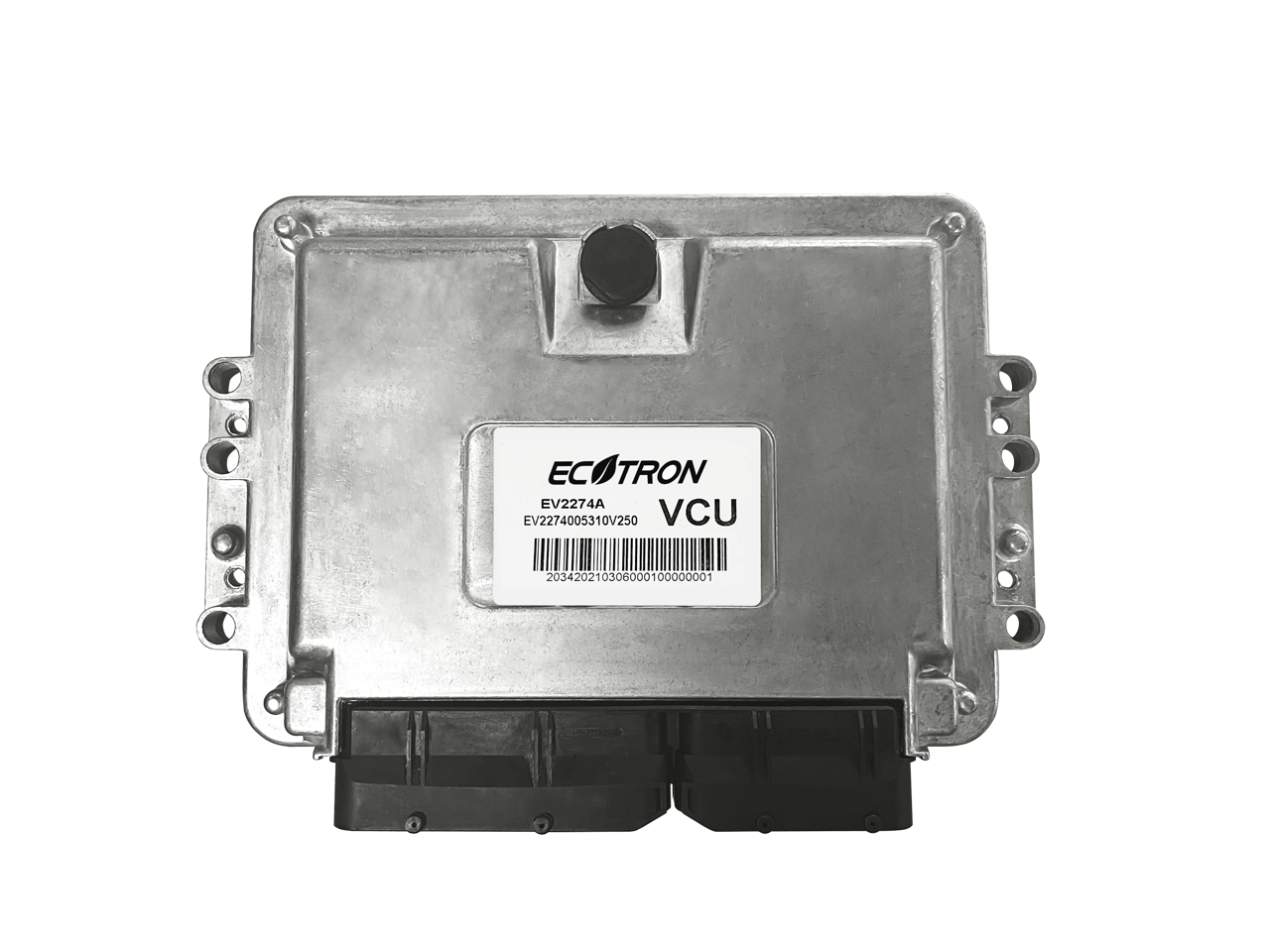
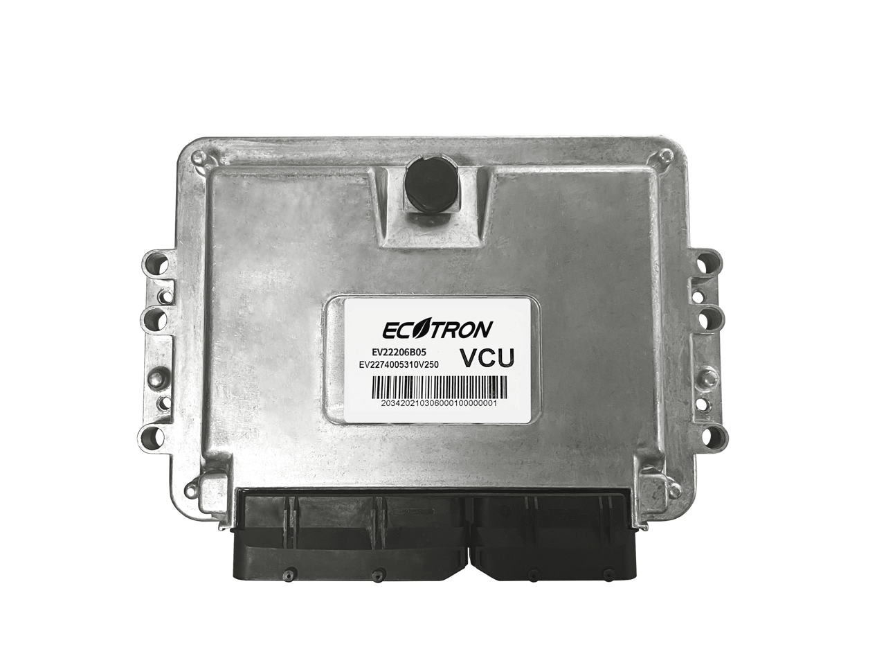
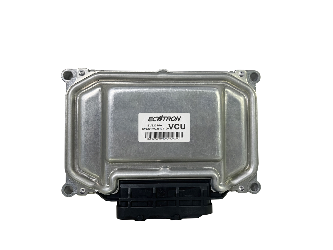
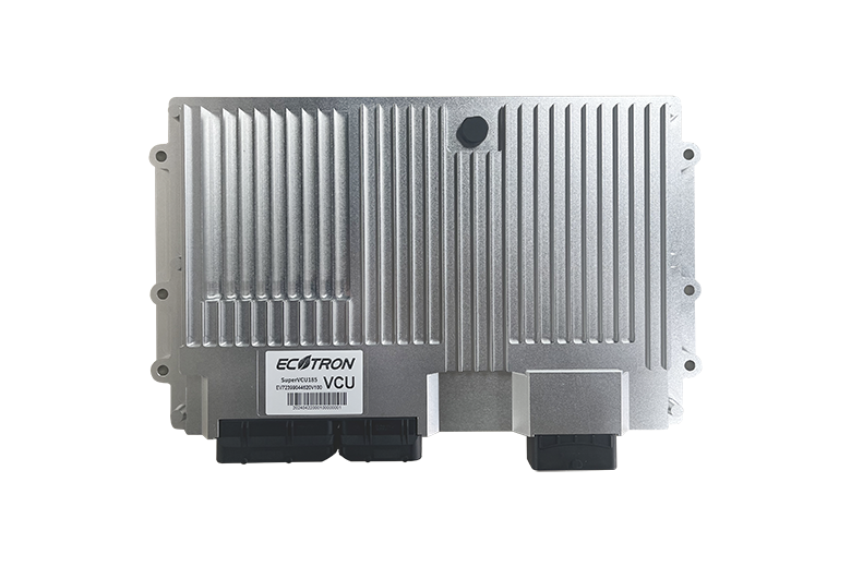
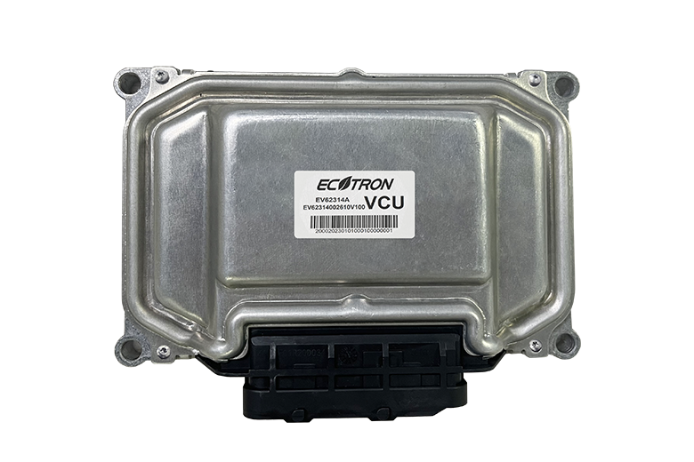
The Vehicle Control Unit, or VCU, is the supervisory controller for electric or hybrid vehicles.
Ecotron offers low cost but high performance VCUs based on NXP microchips, such as the S32K (ASIL-D rated), or Infineon microchips, such as the TC397 and TC399 (ASIL-D rated).
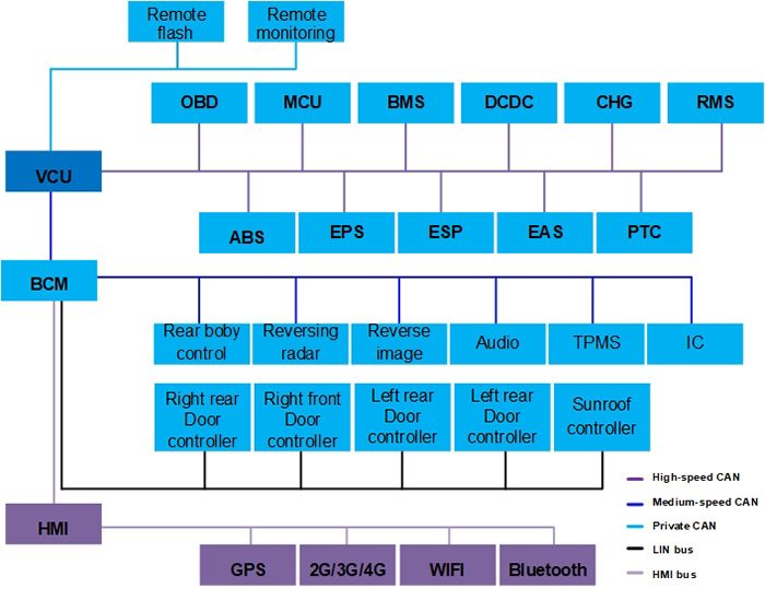
Ecotron VCUs are future oriented. The standard VCU comes with 3+ CAN bus. High performance VCUs come with FlexRay and optional Ethernet functions. All VCUs are capable of OTA (Over-The-Air) programming.
Features
- Ecotron VCU is designed with ISO26262 functional safety in mind, and comes with a main chip and a monitor chip built-in, for safety monitoring
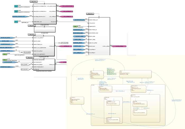
- Ecotron VCU comes with the basic software, or BSW, support all typical input / output drivers for vehicle controls. The BSW is encapsulated in the MATLAB/Simulink environment, and the user can develop the control system with 100% model based design methods
- The VCU hardware is abstracted from the application software and relieves the controls engineer from the challenge of the microprocessor configuration and embedded real-time software
- Ecotron VCU comes with a CAN bus based reprogramming tool, and with properly configured protocols, it can be used for OTA programming
- Ecotron VCU supports the CCP/XCP based CAN bus calibration tools, like INCA, CANape, as well as the cost effective EcoCAL, developed in-house
Applications
- Electric cars
- Electric trucks
- Electric bus, commercial vehicles
SBC:
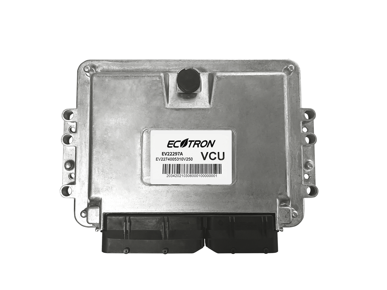
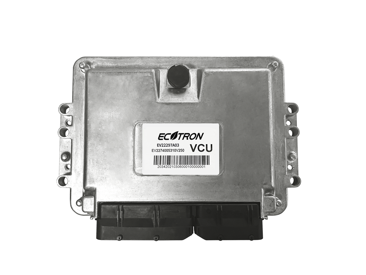
| Functions | EV22297A | EV2274A | EV2274KAH | EV22297A03 |
|---|---|---|---|---|
| Main chip | Infineon TC297TP: 300MHZ, Flash 8M, SRAM 728KB | NXP SPC5744P: 200MHz, Flash 2.5MB, SRAM 384K, floating point capability | ST SPC574K72E7: 160MHz, Flash 2.624MB, SRAM 64KB, floating point capability | Infineon TC297 TP: 300MHz, Flash 8MB; SRAM 728KB; EEPROM 512KB supports floating point arithmetic |
| Monitor chip | SBC: TLF35584QVVS2 | SBC: MC33CFS6500 | / | SBC: TLF35584QVVS2 |
| Supply voltage | DC 12V/24V | |||
| Peak voltage | DC 36V | |||
| Reprogramming | Bootloader, UDS protocols | Bootloader, CCP protocols | Bootloader, CCP protocols | Default: UDS Protocol, supports CCP |
| CAN Bus | 6 channels,4 channels CANFD, 2 channels specific frame wake up | 3 channels, 1 channel specific frame CAN wake up, 1 channel arbitrary frame CAN wake up | 3 channels, CANA support wake up at any frame | 6 channels: CANA, CANB, CANC, CAND support ISO CANFD;CANE, CANF supports regular CAN and specific frame wake-up |
| LIN Bus | 2 channel | 1 channel | / | 1 channel |
| EEPROM | 512K | 64K | 64K | 512K |
| Sensor supply output | 6 channels, 5V; 4 channels, 8V | 5 channels, 5V | 3 channels | 9 channels, 5V |
| Analog Input | 22 channels | 15 channels | 23 channels | 22 channels |
| Digital Input | 13 channels | 14 channels | 16 channels | 13 channels |
| Frequency signal input | 6 channels | 4 channels | 6 channels | 4 channels |
| Low-side driver | 7 channels @ 0.5A, 7 channels @ 1A, 4 channels @ 3A, 4 configurable as PWM output | 11 channels @ 0.5A, 4 configurable as PWM output 5 channels @1A, 2 channels @ 3A |
16 channels @ 0.25A, 2 could be configured as PWM outputs, 2 channels @ 0.25A, 2 configurable as PWM outputs |
6 channels @ 1.5A, 6 channels @ 0.8A, 4 channels @ 0.4A, 10 channels @ 0.16A, 7 configurable as PWM output |
| High-side driver | 3 channels @ 0.5A, 5 channels @ 1A, 2 configurable as PWM output, 2 channels @ 3A | 2 channels @ 0.5A, 5 channels @ 1A 2 configurable as PWM output, 2 channels @ 3A |
6 channels @ 1A, 4 configurable as PWM outputs |
4 channels @ 1.5A, 5 channels @ 0.4A, 5 channels could be configured as PWM output |
| Operating temperature | -40 ~ +85℃ | |||
| Storage Temperature | -40 ~ +85℃ | |||
| Working humidity | Satisfying 0 ~ 95%, noncondensing | |||
| Protection category | IP67 | |||
| Pin number | 121 Pin | |||
| Dimensions | 207×150×42mm | |||
| Housing Material | Aluminum | |||
| Weight | ≤700g | ≤600g | ≤700g | |
| Mechanical characteristics | Vibration, shock, drop test done according to ISO16750 | |||
