EcoCoder
EcoCoder is an enhanced auto-code generation library sitting on top of the generic Matlab/Simulink. It links directly to the target controller. It integrates the code generation, the compiling, and the executable generation in one click.
System support:
Windows XP, Windows 7, Windows 10, & Windows 11
Supported versions of MATLAB:
MATLAB 2010b and above
MATLAB component requirements:
① MATLAB, ② Simulink, ③ MATLAB Coder, ④ Simulink Coder,
⑤ Embedded Coder, ⑥ Stateflow, ⑦ Stateflow Coder
![]()
Basic EcoCoder library and S-Function
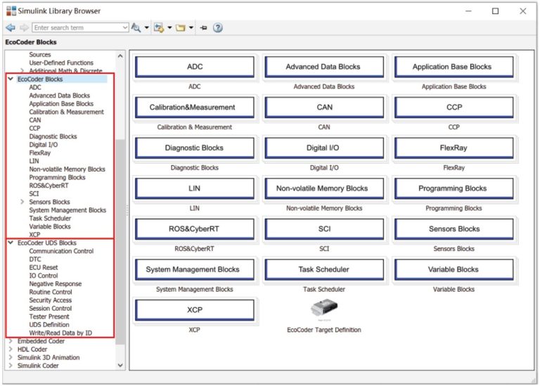
When you install EcoCoder, the installation process will automatically add all EcoCoder’s library blocks and S-functions to Simulink.
It will capture all the hardware drivers with EcoCoder S-functions, including ADC drivers, CAN drivers, digital IO drivers, PWM drivers etc. It’ll also capture the real-time operating systems with EcoCoder task scheduler S-function.
It links the application software, i.e. Simulink model, to the hardware drivers via EcoCoder library blocks and S-functions in Simulink environment.
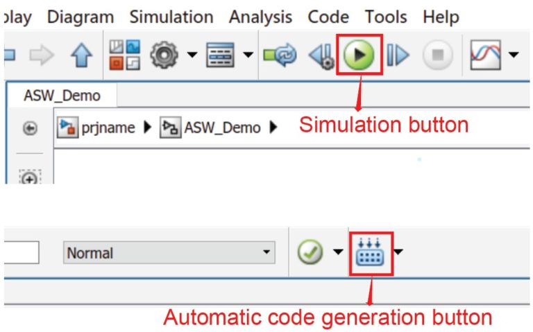
When you run simulation in Simulink, it verifies model and software integrity.
After you click “code generation” button, EcoCoder will generate the microprocessor compatible codes automatically, which will invoke compiling and linking process, running in the background using a compiler, e.g. CodeWarrior, to compile the application code and hardware driver code together and generate the executable codes.
Files Generated by EcoCoder's Compiling Process
- Machine executable file, e.g. .MOT and .HEX file for NXP S32, MPC57xx/56xx series or Infineon TC2xx/3xx series microprocessors
- .A2L file, which is a descriptive file containing all the necessary info for the calibration tool to interpret the controller protocols and compatible with calibration software such as INCA/CANape
- .CAL file, containing only calibration data, without the program
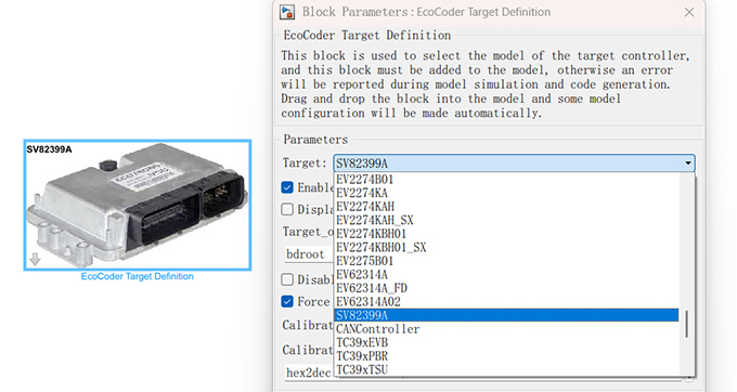
EcoCoder Target Definition
After dragging this block into the Simulink model, EcoCoder will automatically configure the model parameters according to the target you selected.
ADC
ADC(Analog-Digital-Converter) block is used to collect the input of the analog signal. There are three versions of ADC blocks for collecting the original AD value, the fixed point voltage value, and the floating point voltage value.
CAN
CAN block is used to define CAN communication, including CAN channel configuration, data interpretation, data packing, message receiving and sending, CAN wake-up configuration and CAN diagnostics etc.
Digital IN/OUT
Digital IN/OUT blocks can manage digital input and output signals, including digital input and output, frequency (PWM) signal input and output, wake-up signal input and H-bridge output control.
LIN
LIN communication block is used to define LIN channel parameters, including LIN bus status and data sending and receiving.
Task Scheduler
Task Scheduler is used to define task type and priority and monitor the tasks.
Non-Volatile Memory
Non-Volatile Memory block is used to define fixed NVM variables and non-fixed NVM variables, including variable type definition, variable initialization, data read/write, data initial value definition, variable address acquisition.
Diagnostic
Diagnostic block is used to enable the user to perform hardware level troubleshooting, including the diagnostic info of high/low side driver, power block, and H-bridge.
Calibration & Measurement
Calibration & Measurement block is used to define calibration and measurement variables. Calibration variables can be single value, 1-D array and 2-D array.
System Management
System Management blocks mainly include system power management, watchdog operation, system free running counter operations etc.
CCP
CCP block is used for CCP initialization, SeedKey definition (calibration, measurement and flashing) and seed task trigger and sending.
Programming
Programming block is used for online programming function definition, programming parameter definition etc.
Advanced Data
Advanced Data blocks mainly include special memory operation blocks, including OTP operation, flash analog EEPROM, and read data by address.
Application Base Block
Application Base blocks mainly include basic algorithm blocks that might be used for application model design.
XCP
XCP blocks mainly include XCP initialization and parameter configurations.
FlexRay
FlexRay blocks mainly include FlexRay communication definition, status acquisition, status restoration, message sending and receiving.
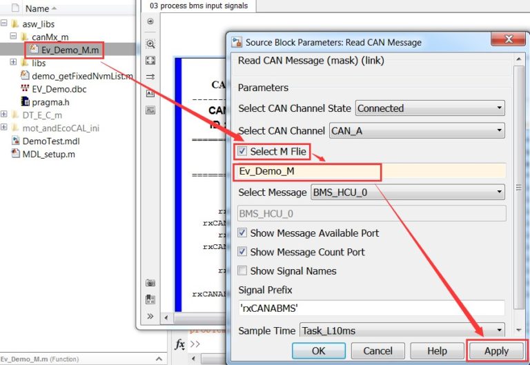
CAN Protocol Implementation
You can convert DBC file to .m file through EcoCAN, then select the .m file and the CAN message in the .m file in the CAN block in EcoCoder. CAN signals will be displayed when selecting and it will be connected to the signal in the model after selected.
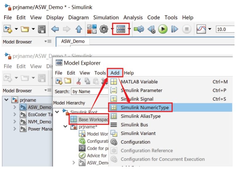
User Defined Variable
User Defined Variables can be defined either by EcoObj in .m file, or by Model Explorer in MATLAB. You can click “Simulink NumericType” in Model Explorer->Base Workspace to define User Defined Variables.
Auto-Code Generation
After the model simulation passes, you can generate executable files by using shortcut “Ctrl+B” or clicking on the button below.